
Understanding Injection Molding Defects at the Root
Many injection molding professionals have encountered the same situation: short shots, silver streaks, flash, and other defects appear, and the first response is often to increase injection pressure or raise the melt temperature. Sometimes the defect disappears-but after changing the material batch or mold, the same problem may return.
In many cases, machine adjustments only address the visible symptoms rather than the underlying cause. Without understanding the mechanisms behind injection molding defects, repeatedly changing processing parameters makes it difficult to achieve consistent and stable mass production.
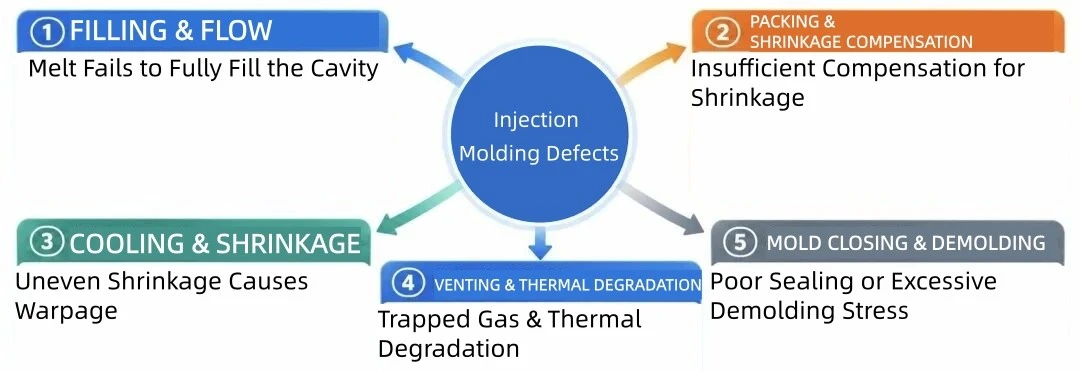
Most injection molding defects can be traced back to five fundamental categories:
- ① Filling & Flow Imbalance
- ② Gas & Volatile Control Imbalance
- ③ Cavity Pressure & Packing Imbalance
- ④ Material State & Interfacial Bonding Imbalance
- ⑤ Cooling, Shrinkage & Orientation Imbalance
Short Shot · Jetting · Flow Marks
The melt must completely fill the mold cavity before premature freezing occurs. When material flowability is insufficient, runner or gate resistance is excessive, or the injection speed profile is poorly designed, a range of flow-related defects can occur.
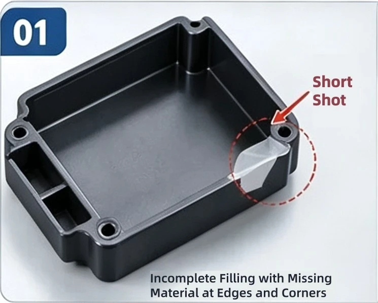
Short Shot
Incomplete cavity filling caused by insufficient flowability, excessive flow resistance, poor venting, or unstable material feeding.
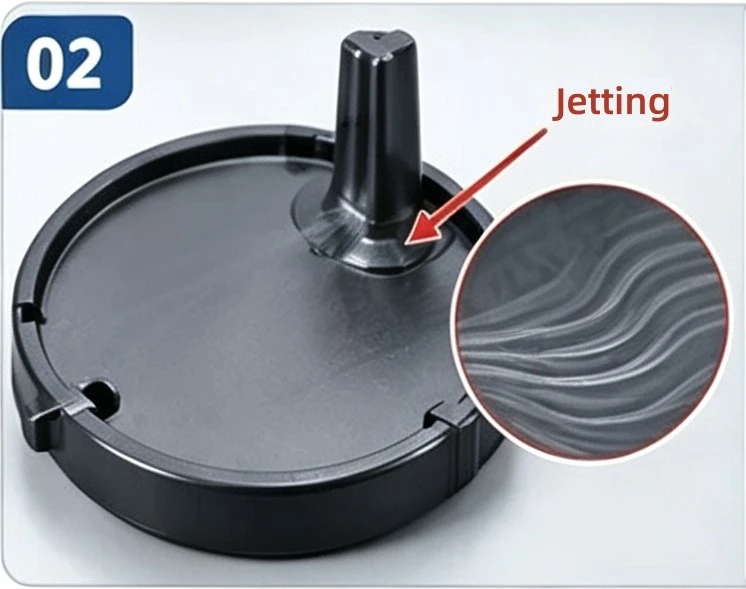
Jetting
High-speed melt injection through the gate creates an unstable flow pattern. Optimize gate-area injection speed and guide the melt to flow smoothly along the mold wall.
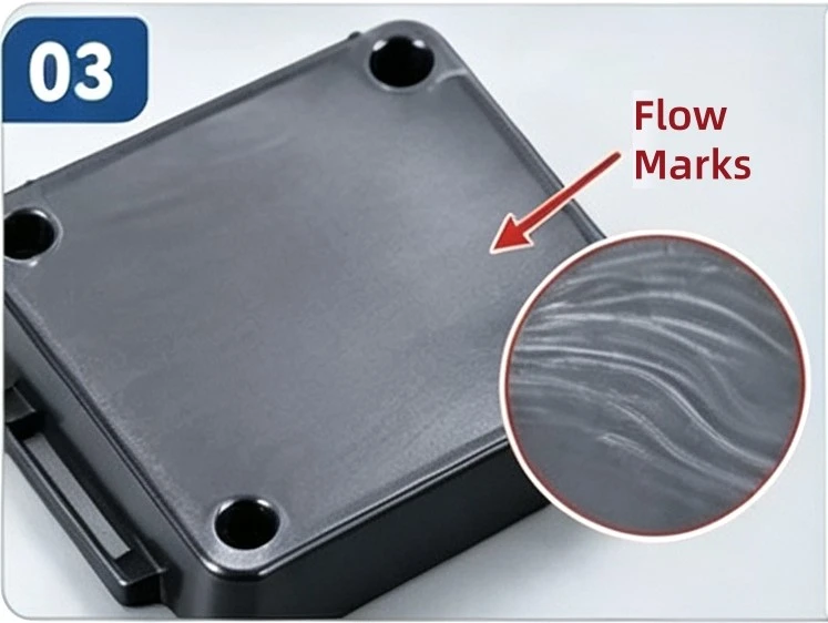
Flow Marks
Uneven melt-front advancement caused by low mold temperature, improper injection speed, sudden flow-section changes, or cold material.

Gate Blush
Localized whitening near the gate, often related to excessive shear. Reduce gate-area injection speed and optimize gate geometry.
Three Sources of Gas in Injection Molding
Gas inside the mold can generally come from three sources:
① Air originally trapped in the mold cavity
② Moisture carried in with the raw material
③ Volatiles generated during plasticization and decomposition gases produced by thermal degradation
Different gas sources require different corrective actions. They should not be treated as the same problem.
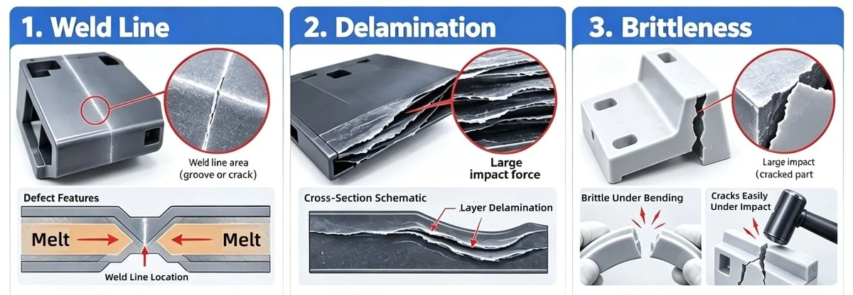
Weld Lines · Delamination · Brittleness
Weld Lines
When two melt fronts meet, a weld line is formed. It is not simply a visible surface mark-the more critical factor is the bonding strength at the interface. A part may show only a faint weld line visually but still fracture during impact testing if the two melt fronts have not fused sufficiently.
Delamination / Peeling
When layers peel away from the surface, material compatibility should be one of the first factors to investigate. Mixing different grades of plastic, contamination from regrind, or the introduction of mold-release agents and oil can weaken interfacial bonding. Simply increasing temperature or pressure may not eliminate the problem; material handling and mixing practices should be traced back to the source.
Brittleness & Fracture
Do not immediately conclude that the material itself is too brittle. Hydrolysis or thermal degradation of the resin, insufficient weld-line strength, excessive residual stress caused by over-packing, and stress concentration at sharp corners can all contribute to brittle fracture.
① Fracture consistently occurs at the same sharp corner or boss: Prioritize part design and melt-flow behavior.
② The entire part becomes brittle: Focus on the material condition, thermal history, and residence time in the screw and barrel.
Warping and Deformation
Warping and deformation can take the form of bending, twisting, inward warping, or outward warping. The main causes include four factors: uneven cooling, uneven packing, molecular or fiber orientation, and constraints imposed by part geometry.
Uneven mold temperatures between the core and cavity sides, blocked cooling channels, or excessive temperature differences between inlet and outlet water can cause different shrinkage rates on the two sides of the part, resulting in warpage.
For glass-fiber-reinforced materials, shrinkage can differ significantly between the flow direction and transverse direction. Gate layout directly influences molecular and fiber orientation, which can consequently change the direction and magnitude of warpage.