
Injection Molding Cooling Time: A Comprehensive Guide
A 3 mm wall thickness does not automatically mean a 15-second cooling time, nor does a 4 mm wall always require 20 seconds.
So why can different materials produce significantly different cycle times at the same wall thickness? And why can blindly shortening cooling time lead to defects such as ejector marks, warpage, and mold sticking?
How to Calculate the Complete Injection Molding Cycle Time?
A Complete Injection Molding Cycle: Total Cycle Time Is Not Simply the Sum of All Individual Times
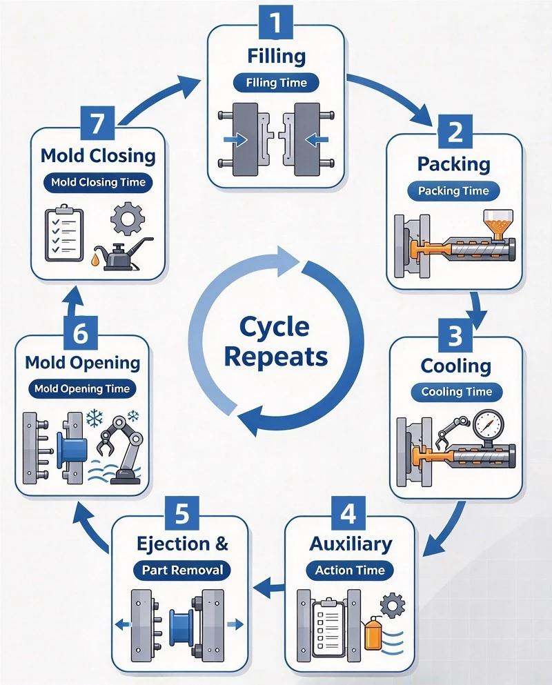
A complete injection molding cycle consists of seven basic operations: mold closing, filling, packing, cooling, mold opening, ejection and part removal, and auxiliary operations.
These correspond to mold closing time, filling time, packing time, cooling time, mold opening time, ejection and part removal time, and auxiliary operation time, respectively.
Several overlapping operations are often overlooked:
① Cooling Begins During the Packing Stage As soon as the molten material enters the mold cavity, heat continuously transfers to the mold. Cooling does not begin only after packing ends.
② Screw Plasticizing and Metering Can Overlap with Cooling In many injection molding processes, screw plasticizing and metering take place while the molded part is cooling, rather than waiting for cooling to finish.
③ Auxiliary Operations Can Overlap with Mold Movements Some auxiliary operations, such as robot part removal and slide reset, can run concurrently with certain mold movements, depending on the machine setup and process sequence.
Ignoring these overlaps and simply adding every stage duration can lead to double-counting, resulting in a calculated cycle time that is significantly longer than the actual production cycle.
Cooling: The Stage That Takes Up the Largest Share of the Cycle
For most thermoplastics, cooling accounts for the largest proportion of the overall molding cycle and represents a key opportunity for cycle-time reduction.
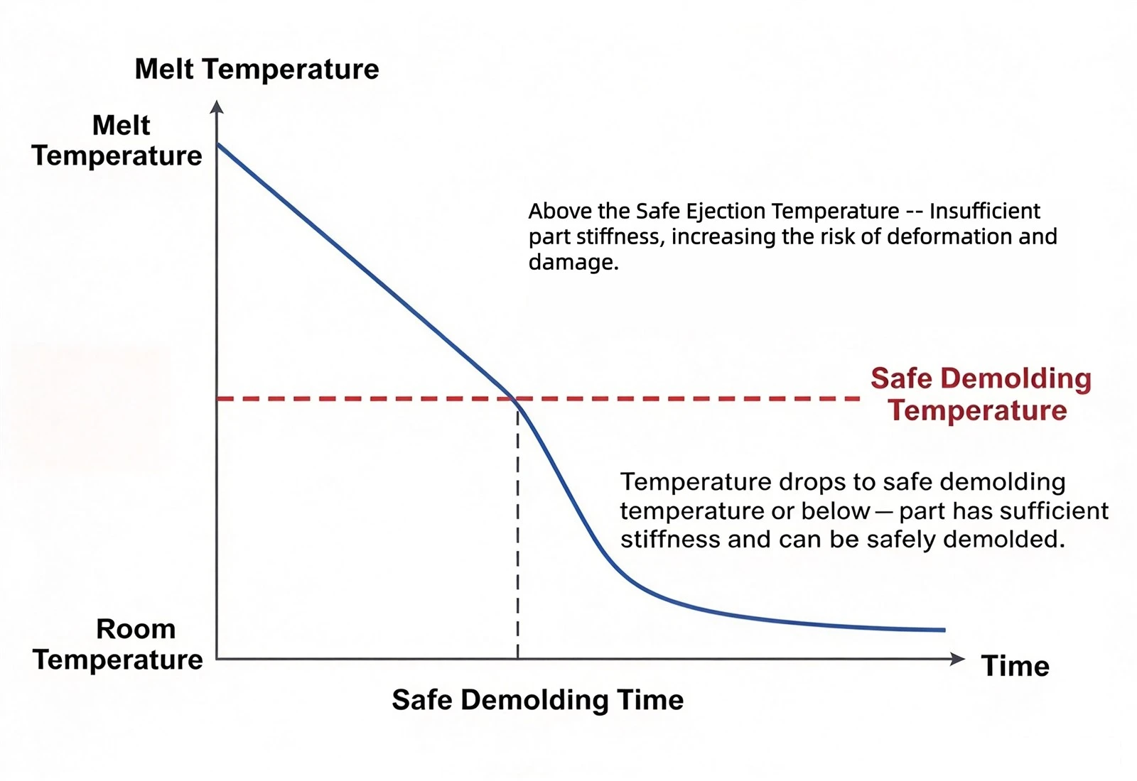
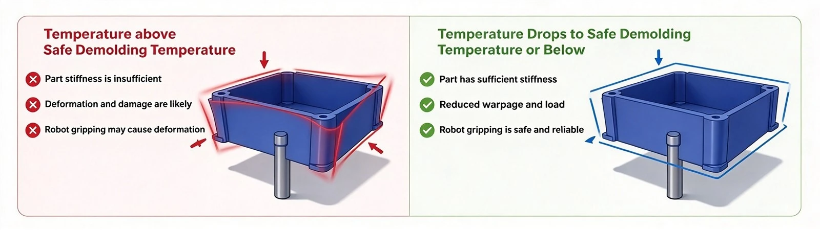
When molten plastic enters the mold cavity, its temperature is close to the melt temperature, and its stiffness is very low. If the mold opens and the part is ejected too early, the component may not have sufficient rigidity, leading to a range of quality defects, including ejector marks, ejector punch-through, mold sticking, surface scratches, warpage, and dimensional instability.
A Key Concept: Safe Ejection Temperature
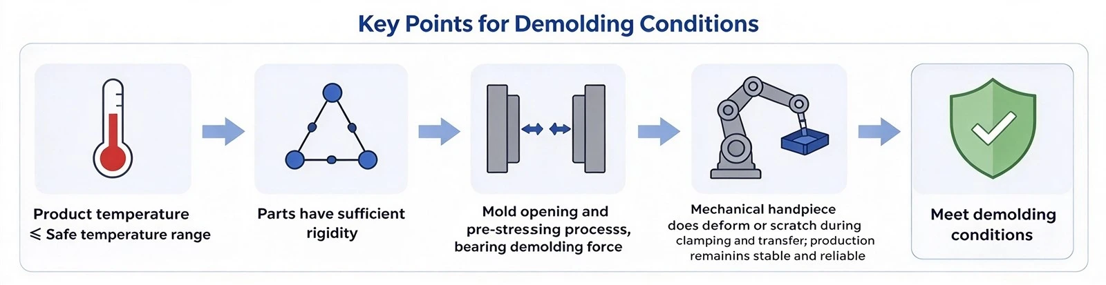
The goal of cooling is not to bring the part down to room temperature. Instead, the part's core temperature must drop to or below the safe ejection temperature, allowing it to develop sufficient stiffness to withstand the mechanical loads during mold opening, ejection, and robotic part removal. Once these conditions are met, the part is ready for ejection.
Wall Thickness: The Most Influential Factor
Fourier's transient heat conduction equation provides the fundamental theoretical basis for injection molding cooling calculations. One key parameter is thermal diffusivity (α), which describes how quickly temperature changes propagate through a material. It is determined by the material's thermal conductivity, density, and specific heat capacity.
For a simplified injection-molded flat plate, an approximate theoretical cooling-time formula can be derived. The key finding is that theoretical cooling time is proportional to the square of the effective wall thickness.
In other words, cooling time increases with the square of wall thickness, not linearly.
Complete Closed-Loop Process
1. Calculate the Theoretical Cooling Time: Identify the maximum effective wall thickness and apply Fourier's equation to establish a theoretical cooling-time baseline.
2. Verify the Assumptions of the Theoretical Model: Check for uneven wall thickness, boss features, and localized hot spots to determine whether the simplified flat-plate model is applicable.
3. Conduct Cooling Analysis: Use simulation software to evaluate hot-spot distribution, temperature fields, and part temperature at the end of cooling.
4. Gradually Reduce Cooling Time During Mold Trials: Start with a relatively long cooling time and shorten it incrementally.
5. Inspect Ejection Conditions: Check for defects such as ejector marks, ejector punch-through, mold sticking, surface scratches, and excessive part softness.
6. Verify Dimensional Stability: Recheck shrinkage, flatness, warpage, and critical dimensions to ensure dimensional consistency.
7. Check Part Weight and Process Stability: Monitor variations in part weight and inspect for any abnormalities in appearance.
8. Validate Thermal Equilibrium During Continuous Production: Run continuous production trials to confirm that mold temperature, cooling water temperature, cycle time, and product quality remain stable.