
LFT Injection Molding Guide: How to Maximize Fiber Length and Part Strength
You've selected the right LFT material. The fiber content is correct. The resin system is optimized. But when the parts come out of the mold, the mechanical properties are nowhere near the data sheet values.
What went wrong? Fiber breakage during injection molding - the single most overlooked factor in LFT processing.
This guide covers the key process parameters, equipment choices, and mold design principles that determine how much of the original fiber length survives the molding process - and how to maximize it.

The Problem: Short Fibers Don't Reinforce
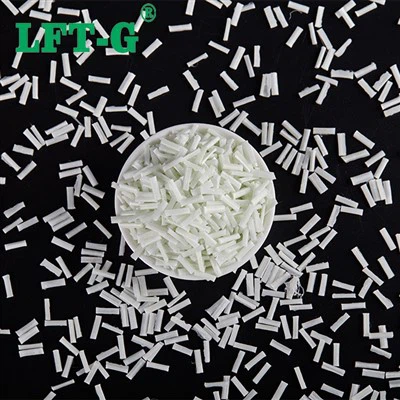
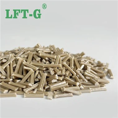
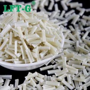
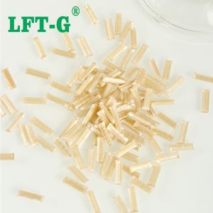
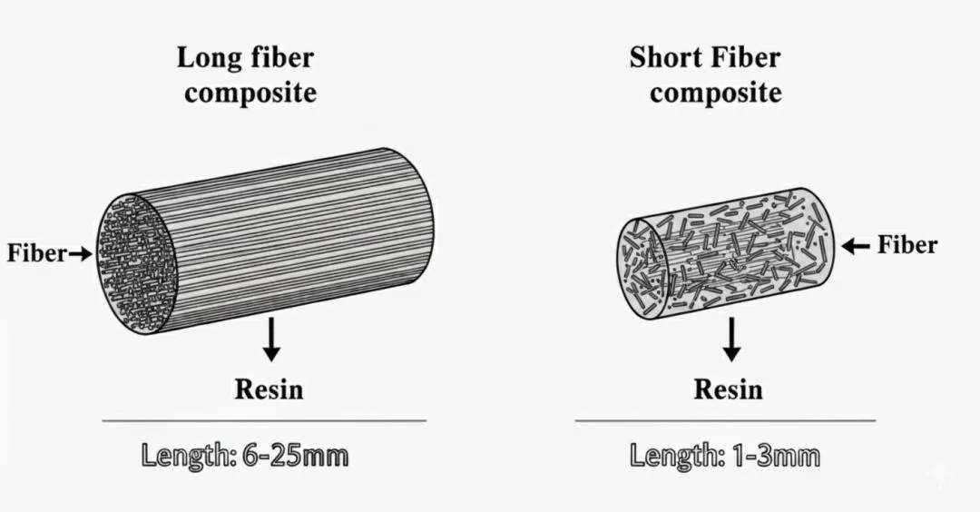
Every LFT pellet starts with 10–12mm continuous fibers - long enough to form a reinforcing network that delivers high impact resistance, creep resistance, and fatigue life. But during injection molding, the screw, nozzle, and gate all act as fiber-breaking machines.
When fiber length drops below 2–3mm, the material stops behaving like a true LFT and starts behaving like a short-fiber compound. The reinforcing network breaks down. Impact resistance drops. Creep accelerates. Fatigue life shortens.
The data: Studies show that fiber length reduction from 10mm to 2mm can reduce impact strength by 40–50% and fatigue life by over 60%. Processing conditions almost entirely determine the difference between "excellent" and "mediocre" LFT performance.
-
Process Parameters - The Big Three
Injection Speed
The rule: slower is better. High injection speeds generate extreme shear forces that snap fibers like twigs. The melt flows through the nozzle and gate at high velocity, creating a "fiber shredding zone" that can reduce average fiber length by 50% or more.
✅ Best Practice
|
❌ Avoid
|
Back Pressure
The rule: keep it as low as possible. Back pressure exists to ensure melt homogeneity, not to chop fibers. Every extra bar of back pressure increases shear and fiber breakage. The difference between 5 bar and 15 bar back pressure can reduce average fiber length by 30%.
✅ Best Practice
|
❌ Avoid
|
Melt Temperature
The rule: stay in the middle of the recommended range. Too low and the melt is viscous, increasing shear. Too high and the polymer degrades, breaking the fiber-matrix bond. Both scenarios reduce effective fiber reinforcement.
✅ Best Practice
|
❌ Avoid
|
-
Screw Design - The Right Tool for the Job
Not all injection molding screws are suitable for LFT. Standard screws are designed for short-fiber materials and will aggressively break long fibers during plastication.
| Screw Feature | Standard Screw | LFT-Optimized Screw |
|---|---|---|
| Compression ratio | 2.5–3.0:1 (aggressive) | 1.8–2.2:1 (gentle) |
| Feed section length | Short | Extended (40–50% of screw length) |
| Mixing elements | Intensive mixing sections | Gentle mixing or no mixing sections |
| Check ring | Standard design | Low-shear, free-flow design |
Key recommendation: If you are processing LFT materials regularly, invest in a dedicated LFT screw. The cost of the screw is quickly recovered through improved part quality, reduced scrap, and the ability to achieve the mechanical properties your design requires.
-
Gate and Runner Design - Where Fibers Break Last
The gate is the final obstacle between the melt and the cavity - and often the site of maximum shear. Poor gate design can negate all the care you've taken with process parameters and screw selection.
Avoid sharp corners and abrupt transitions
Every sharp edge in the runner or gate is a "fiber chopper." Use radiused corners and gradual taper transitions to minimize shear.
Use larger gates
A gate that's too small creates high shear rates that break fibers. Use the largest gate size that is practical for the part and cycle time.
Gate location affects fiber orientation
Fibers tend to align in the flow direction. In a tensile stress application, this is ideal. In a multi-directional stress application, consider multiple gates or film gates to create more balanced fiber orientation.

-
How to Validate Your Fiber Length Retention
You can't manage what you don't measure. If you want to truly optimize your LFT molding process, you need to measure fiber length distribution in the final part.
- Burn-off test: Burn the polymer away at 600°C, collect the remaining glass fibers, and measure their length distribution under a microscope. (Carbon fibers require a different method - ask your LFT supplier for guidance.)
- Target: Your goal should be to retain at least 70% of the original fiber length in the final part. Many processors achieve 60% or less - and their parts underperform accordingly.
- Compare: If your fiber length retention is below target, work through the parameters above - process conditions, screw design, gate geometry - to find and eliminate the sources of excessive breakage.
Pro tip: LFT-G® offers fiber length analysis as part of our technical support. We can test your molded parts and provide a detailed report on fiber length distribution - helping you pinpoint exactly where your process is falling short.
Summary: Control the Process, Unlock the Performance
LFT materials contain the reinforcement you need for demanding applications. But the reinforcement only delivers its potential if fiber length is preserved through the molding process.
- Injection speed: Slow is good. Multi-stage is better.
- Back pressure: As low as possible. Monitor, don't guess.
- Melt temperature: In the middle of the range. Check with a pyrometer.
- Screw design: Use a dedicated LFT screw with low compression ratio.
- Gate design: Large gates, radiused corners, smooth transitions.
- Validation: Measure fiber length in the final part. Optimize. Repeat.
The result: Parts that deliver the mechanical performance shown on the data sheet - and customers who trust your ability to turn a good material into a great component.

Xiamen LFT Composite Plastic Co., Ltd. is a global supplier of long-fiber-reinforced thermoplastics with 20+ years of innovation. We specialize in LFT‑PP, LFT‑PA, LFT‑PPS, and LFT‑Elastomers – offering high‑strength, lightweight alternatives to metal for automotive, aerospace, and industrial applications.