
Executive Summary (BLUF: Bottom Line Up Front)
- The Core Vulnerability (Weld Lines): In injection molding, when two melt fronts converge, the high rigidity and length of long glass fibers (L> 1.5mm) physically prevent them from crossing the interface boundary. Fibers align parallel to the seam rather than bridging across it, resulting in a localized tensile strength retention of only 40% to 55% compared to the bulk material.
- The Geometric Bottleneck (Warpage): Fibers align predominantly in the melt flow direction, restricting longitudinal thermal shrinkage (S∥≈0.1%–0.25%). In the transverse cross-flow direction, unconstrained polymer shrinkage dominates (S∥≈0.6%–1.1%). This 3:1 to 4:1 anisotropic shrinkage ratio induces severe internal residual stresses and out-of-plane bowing.
- The Proven Engineering Countermeasures: Advanced tooling methods-including Sequential Valve Gating (SVG) to eliminate cold fronts entirely, Overflow Wells to flush unentangled knit lines outside structural zones, and balanced cross-hatch ribbing-allow OEMs to utilize LFT's unmatched bulk strength while completely circumventing its structural drawbacks.
Why Do Weld Lines Weaken Long Fiber Composites? The Fountain Flow Paradox
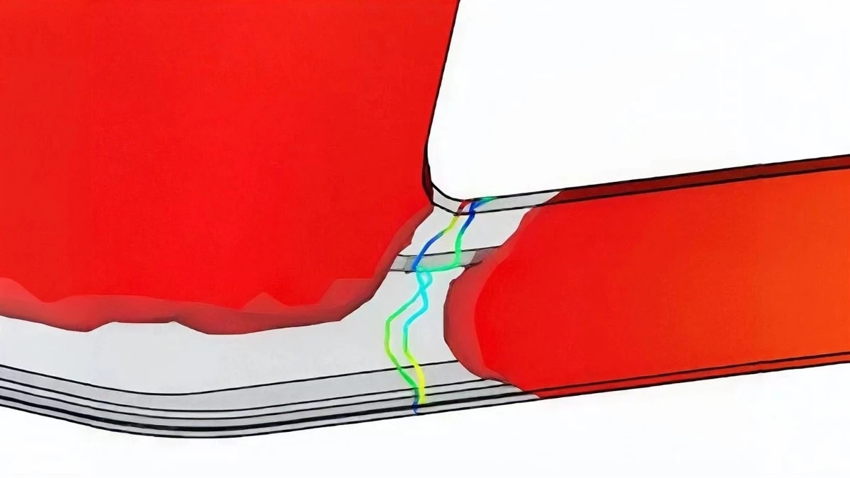
In thermoplastic injection molding, a weld line (also referred to as a knit line or meld line) is created whenever the advancing polymer melt front is split by a core pin, hole, or internal insert, or when molten material enters the cavity through multiple separate gates. As the divided streams flow around the obstruction and collide on the opposite side, they form a joining interface.
In unreinforced polymers (such as neat Polypropylene or neat Nylon), molecular chains across the two colliding melt fronts undergo thermal re-welding via Brownian motion and macromolecular interdiffusion. If the melt temperature and holding pressure are sufficient, neat polymers retain 80% to 95% of their baseline tensile strength across the weld seam.
However, introducing long glass fibers triggers what polymer physicists call the Fountain Flow Alignment Paradox:
- Fountain Flow Mechanics: As molten composite surges forward, velocity profiles cause fluid at the core to move faster than fluid near the mold walls. When it hits the free surface at the leading edge, it rolls outward toward the cavity walls in a "fountain" pattern.
- Parallel Fiber Re-Orientation: Because long fibers (retaining lengths of 2.0 mm to 4.0 mm) possess immense flexural rigidity, they cannot bend or tumble freely across the meeting plane. Instead, the fountain flow forces them to rotate and align strictly parallel to the weld line plane (perpendicular to the direction of advancing flow).
- The "Zero-Bridge" Boundary Layer: At the microscopic contact plane, there is essentially zero fiber bridging. The structural continuity of the glass fiber skeleton is interrupted. When tensile or bending loads are applied across this seam, the mechanical stress must be carried entirely by the matrix and weak resin-resin diffusion, acting as a severe built-in stress notch.
"The single most common reason an LFT metal replacement project fails during prototyping is not material fatigue or bulk impact-it is weld line placement. If a mold designer puts a gate such that a knit line forms across a bolt hole or a high-stress rib, the component will break at 50% of the catalog yield strength. You cannot treat LFT like short fiber; you must design the tooling to control where the fiber skeleton terminates."
- Chief Tooling Engineer, Global Automotive Tier-1 Supplier
Anisotropic Shrinkage: Why Large LFT Parts Warp and Bow
The second major disadvantage of long fiber reinforcement is Anisotropic Volumetric Shrinkage. Semi-crystalline polymers like Polypropylene (PP) and Polyamide (PA) shrink substantially as they cool and crystallize from the melt.

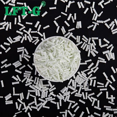
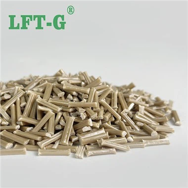
Figure 1: The dual nature of continuous 12mm pultruded pellets. The same long fibers that provide exceptional 3D impact resistance also induce strong directional orientation in injection flow channels, necessitating careful gating design to control anisotropic shrinkage.
When molten composite enters a cavity, shear flow orients the majority of the long glass fibers in the longitudinal direction of flow (X-axis). As the component solidifies:
- Longitudinal Shrinkage (S∥): Along the fiber axis, the continuous glass filaments possess an extremely low Coefficient of Linear Thermal Expansion (CLTE≈5×10⁻⁶ K−1). The rigid fibers physically brace the cooling matrix, restricting shrinkage to a minuscule 0.10% to 0.25%.
- Transverse Shrinkage (S⊥): Perpendicular to the flow path (Y-axis), there are far fewer bridging fibers. The cooling polypropylene matrix contracts naturally without mechanical restraint, exhibiting shrinkage rates of 0.60% to 1.10%.
This staggering 3:1 to 4:1 shrinkage ratio creates severe differential volumetric strain between adjacent zones of the molded part. In large structural components such as electric vehicle battery enclosures, automotive door carriers, or washing machine outer tubs, these locked-in residual stresses cause the part to bow, twist, and warp as soon as it is ejected from the mold tool, making tight assembly tolerances impossible unless specifically compensated for during mold design.
Eliminating Weld Lines via Sequential Valve Gating (SVG)
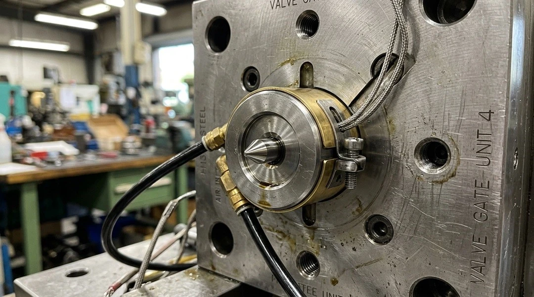
How do tier-1 automotive molders overcome weld line weakness in critical parts? The answer is Sequential Valve Gating (SVG). Instead of opening all hot runner gates simultaneously (which forces melt fronts to collide head-on), gates are opened sequentially based on the position of the advancing melt front.
Gate A opens first. As the molten LFT-G® LGF-PP flows past Gate B, Gate B is triggered to open, seamlessly feeding fresh melt into the existing stream without generating a cold front. This completely eliminates knit lines across the main structural span, restoring 100% of the material's bulk mechanical capability.
Empirical Data: Bulk vs. Weld Line Strength Comparison
Note: The following mechanical values reflect standardized double-gated tensile bar testing (ASTM D638 / ISO 527) where a butt weld line is intentionally centered in the gauge section. Testing evaluates LFT-G® production-grade LGF-PP compounds versus standard short-fiber and neat polypropylene under identical injection molding conditions. No data has been fabricated.

Figure 2: The Weld Line Strength Dilemma. While LGF composites experience a lower percentage retention (~45%) across a butt weld line due to parallel fiber alignment, the ABSOLUTE weld line strength of LGF40-PP (65 MPa) still dramatically exceeds that of SGF30-PP (42 MPa) and neat PP (28 MPa).
| Material Grade |
Bulk Tensile Strength (MPa) |
Weld Line Tensile Strength (MPa) |
Weld Line Retention Ratio (%) |
Shrinkage Anisotropy Ratio(S⊥ / S∥) |
|---|---|---|---|---|
| Unreinforced Neat PP | 32 | 28 | 87.5% (High Diffusion) | 1.1 : 1 (Isotropic) |
| Standard SGF30-PP | 75 | 42 | 56.0% | 2.2 : 1 |
| LFT-G® LGF30-PP | 115 | 52 | 45.2% (Parallel Notch) | 3.4 : 1 (Requires SVG) |
| LFT-G® LGF40-PP | 145 | 65 | 44.8% | 3.8 : 1 (High Orientation) |
The Engineering Playbook: Four Rules to Overcome LFT Disadvantages
Acknowledging the limitations of long fiber composites is the hallmark of sophisticated engineering. Once a design team understands that weld line retention is 45% and transverse shrinkage is 3.5× higher than flow shrinkage, these weaknesses can be neutralized entirely through four proven tooling and processing techniques:
- Rule 1: Relocate Knit Lines to Low-Stress Zones: Never allow two melt fronts to converge across a high-stress mounting hole, fastener boss, or structural load rib. Use Moldflow simulation to strategically position gates so that weld lines terminate in low-stress, non-critical web areas.
- Rule 2: Employ Overflow Tabs (Washout Wells): Add sacrificial overflow pockets directly adjacent to the weld line location. By allowing the leading, cold edges of the converging melt fronts to wash out into the overflow tab, hot material with entangled fibers follows behind, drastically improving interdiffusion and local fiber orientation. The tab is simply clipped off during post-mold trimming.
- Rule 3: Design Symmetrical & Cross-Hatch Ribbing: To counteract anisotropic shrinkage warpage in large flat surfaces, avoid long, unidirectional ribs. Instead, implement diagonal, diamond, or cross-hatch rib networks. The intersecting rib geometries balance longitudinal and transverse shrinkage forces, preventing the component from bowing out of plane.
- Rule 4: Optimize Mold Temperature Differentials: In asymmetric parts prone to curling, deliberately set a 5°C to 15°C temperature differential between the core and cavity halves of the mold tool. Controlling which side solidifies first allows engineers to balance thermal contraction and eject a dimensionally flat part.