
How to Choose the Right Wall Thickness for LFT Parts
A practical design guide for long fiber thermoplastics - from wall thickness ranges to rib proportions and fiber orientation.
LFT is not a drop-in replacement for short-fiber plastics or metal. The long fibers require different design rules - particularly when it comes to wall thickness. Too thin, and the fibers cannot orient properly, leading to weak spots. Too thick, and cooling becomes uneven, causing internal voids and extended cycle times.
This guide covers the recommended wall thickness range, why uniformity matters more than the absolute value, how to use ribs effectively, and how wall thickness interacts with fiber orientation. These are practical rules you can apply directly to your next LFT part.
1. The Recommended Wall Thickness Range
For most LFT applications, the optimal wall thickness falls between 2mm and 4mm. This range balances two competing needs: enough thickness for fibers to orient and distribute, and thin enough for efficient cooling and low weight.
Below 1.5mm, fibers cannot orient freely in the flow direction. The result is reduced mechanical performance - particularly impact resistance and creep resistance, which depend on the long fiber network. Thin walls also increase the risk of short shots and flow hesitation.
Above 5mm, cooling becomes uneven. The outer skin solidifies while the core remains molten, leading to internal shrinkage voids and sink marks. Cycle times increase, and the part becomes heavier than necessary - often without a proportional gain in strength.
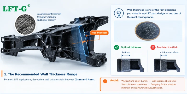
Avoid: Wall sections below 1.5mm · Wall sections above 5mm · Sharp thickness transitions · Designing for the absolute minimum or maximum without justification.
2. Uniformity Matters More Than Absolute Thickness
A part with a uniform 3mm wall is almost always better than a part with a 2mm wall in one area and a 5mm wall in another. Why? Because thickness variations disrupt flow, fiber orientation, and cooling - all at once.
When melt flows from a thick section into a thin section, the flow front accelerates. Fibers that were oriented in the thick section may reorient abruptly, and the resulting internal stresses cause warpage. Uneven cooling between thick and thin sections also creates differential shrinkage, compounding the problem.
The practical rule: keep wall thickness variation within 25% across the part. If a thickness change is unavoidable, use a gradual transition - a taper ratio no steeper than 2:1 (the length of the transition should be at least twice the thickness difference).
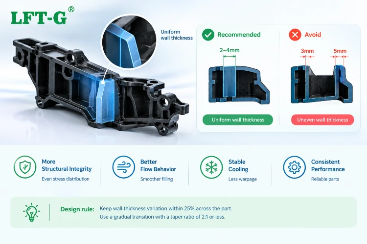
Design rule: Target uniform wall thickness. When variation is unavoidable, limit it to 25% and use gradual transitions with a taper ratio of 2:1 or less.
3. Use Ribs Instead of Thick Walls
When you need more stiffness, the instinct is to increase wall thickness. For LFT, this is usually the wrong move. Thicker walls increase weight, extend cycle time, and risk internal voids - without delivering the stiffness you need.
The better approach is to use ribs. Ribs add stiffness with minimal added weight and without the cooling challenges of thick walls. The long fiber network flows into ribs and reinforces them naturally, making ribs particularly effective in LFT parts.
Three proportions matter:
- Rib base thickness: 50–70% of the nominal wall thickness. This prevents sink marks on the opposite surface while providing structural benefit.
- Rib height: No more than 3× the nominal wall thickness. Taller ribs increase the risk of buckling and create cooling challenges.
- Root radius: At least 50% of the wall thickness. Sharp corners act as stress risers and fiber breakage points; generous radii allow fibers to flow smoothly into the rib.
Rule of thumb: Add ribs rather than thicken walls. A well-designed rib pattern delivers more stiffness per gram than a thicker wall - and avoids the cooling and warpage problems that come with thick sections.
4. Wall Thickness and Fiber Orientation
Wall thickness directly influences how fibers orient during filling - and therefore how the part performs under load.
Thicker walls give fibers more space to orient and distribute. The result is a more three-dimensional fiber network, which improves impact resistance and creep resistance. Thicker sections also allow the fiber network to form more fully, enhancing the part's overall structural integrity.
Thinner walls force fibers into a highly oriented state along the flow direction. This can be beneficial if the part is loaded primarily in that direction - the stiffness and strength in the flow direction can be excellent. But it also creates pronounced anisotropy: properties perpendicular to flow may be significantly lower.
The design implication is straightforward: match wall thickness to the loading direction. If the part experiences multi-directional loads, thicker walls (within the 2–4mm range) help create a more balanced fiber network. If the load is predominantly in one direction, thinner walls with strong flow orientation may be acceptable - provided the design accounts for the anisotropic behavior.
Practical tip: For parts with complex, multi-directional stress, aim for the middle of the thickness range (3mm) and use ribs to add local stiffness where needed. This balances fiber network formation with cooling efficiency.
The Takeaway
Wall thickness is not just a dimension - it's a design decision that affects how the long fibers behave, how the part cools, and how it performs in service. Keep these four principles in mind:
- Target 2–4mm - the sweet spot for fiber orientation and cooling efficiency.
- Uniformity beats absolute thickness - limit variation to 25% and use gradual transitions.
- Ribs over thick walls - use ribs for stiffness with less weight and better cooling.
- Match thickness to loading - thicker for multi-directional loads, thinner for directional loads where anisotropy is acceptable.
LFT-G® provides material-specific wall thickness guidelines for every grade. Our engineering team can review your part design, recommend optimal thickness and rib proportions, and help you avoid common pitfalls. Reach out for design support.

LFT team: ready to support your LFT design
Xiamen LFT Composite Plastic Co., Ltd. is a global supplier of long-fiber-reinforced thermoplastics with 20+ years of innovation. We specialize in LFT‑PP, LFT‑PA, LFT‑PPS, and LFT‑Elastomers – offering high‑strength, lightweight alternatives to metal for automotive, aerospace, industrial, and consumer applications. Our engineering team provides material selection, mold design review, and on-site technical support for customers worldwide. Reach out for a free consultation.