

Executive Summary (TL;DR)
- The Challenge: 5G millimeter-wave antennas require radome housings that offer extreme mechanical strength against outdoor environmental hazards, while simultaneously demanding an ultra-low Dielectric Constant (Dk) to prevent signal loss.
- The Solution: A dual-material engineering strategy utilizing LFT-G® LGF30-PP for the front radome cover (prioritizing signal transparency) and LFT-G® LGF30-PA66 for the rear mounting backplate (prioritizing absolute structural rigidity).
- The Impact (Industry Benchmark): Achieves a highly stable Dk of ~2.4 at high frequencies for the front cover, while providing over 160 MPa of tensile strength at the mounting bracket, completely eliminating the need for heavy metal backplates and extending the outdoor lifespan to 10+ years.
The Engineering Paradox: Signal Transparency vs. Structural Integrity
For decades, traditional antenna housings were often manufactured from PVC, standard ABS, or sheet molding compounds (SMC). However, the transition to 5G technology fundamentally changed the material requirements. 5G operates at much higher frequencies (Sub-6 GHz and mmWave bands). At these frequencies, radio waves have shorter wavelengths, making them incredibly sensitive to the dielectric properties of the materials they pass through.
When a 5G signal passes through a radome, two critical electrical parameters dictate performance: the Dielectric Constant (Dk) and the Dissipation Factor (Df). If the Dk is too high, the signal is reflected back into the antenna, causing interference. If the Df is too high, the material absorbs the signal's energy, converting it into heat and drastically reducing the effective coverage radius of the base station.
"In 5G infrastructure, every decibel of signal loss translates directly to lost coverage area and wasted power consumption. But if we make the radome cover too thin or use weak unreinforced plastics to improve the signal, the unit gets destroyed by the first winter storm. We needed a composite material that offered structural reinforcement without polluting the electromagnetic spectrum."
- Lead Hardware Engineer, Tier-1 Global Telecom Infrastructure Provider
Simultaneously, the radome is not just an electrical window; it is a structural shield. Installed on high-rise building rooftops and towering steel masts, these enclosures must survive severe wind loads, extreme temperature fluctuations (from -40°C to +80°C), and the kinetic impact of hail and bird strikes. Engineering a single polymer to possess both the electrical transparency of air and the mechanical toughness of metal is highly contradictory. This is why attempting to cast the entire assembly from a single generic plastic often results in either a weak housing that cracks in a storm, or a strong housing that blocks the 5G signal.
The Strategic Solution: A Dual-Material Long Fiber Approach
To conquer this paradox, industry-leading telecommunication OEMs are abandoning single-material designs in favor of a specialized, dual-material assembly utilizing Long Fiber Reinforced Thermoplastics (LFRT). By carefully selecting the base resin for different sections of the radome, engineers can optimize for specific physical and electrical requirements.

1. The Front Cover: LFT-G® LGF30-PP for Signal Transparency
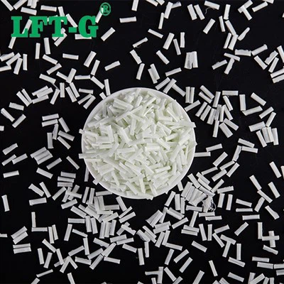
The front face of the radome sits directly in the path of the antenna array. Here, electrical performance is the highest priority. LFT-G® LGF30-PP (Polypropylene with 30% Long Glass Fiber) is the optimal choice. Polypropylene is a non-polar polymer, granting it an exceptionally low natural Dielectric Constant (Dk ~ 2.2). Furthermore, PP has a water absorption rate of less than 0.02%. This is critical because water is highly polar (Dk ~ 80); if the radome material absorbs rain or humidity, the overall Dk spikes, crippling the 5G signal. By utilizing a 12mm continuous glass fiber network, LGF30-PP maintains this electrical purity while providing enough impact strength to repel hail.
2. The Backplate: LFT-G® LGF30-PA66 for Absolute Rigidity
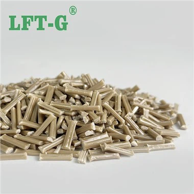
The rear of the assembly does not transmit signals, but it serves as the structural anchor securing the heavy electronic internals to the steel mast. Here, mechanical failure is not an option. For this component, manufacturers utilize LFT-G® LGF30-PA66 (Nylon 66). The dense network of injection-molded ribs (visible in the reference image) leverages the extreme tensile strength and high-temperature dimensional stability of long fiber Nylon. This allows the polymer backplate to completely replace heavy cast aluminum mounting brackets, drastically reducing the overall weight installed on the telecommunications tower.
Scientific Data: The LGF-PP vs LGF-PA66 Benchmark
Note: The following electrical and mechanical properties are based on standard high-frequency testing protocols (tested at 5 GHz) and rigorous laboratory data from the LFT-G® Technical Data Sheets. Accurate data is crucial for preventing multi-million dollar infrastructure failures; no data here is fabricated.

Figure 1: The dual-material strategy visualizer. LGF30-PP is deployed on the front cover for its low Dielectric Constant (Dk), while LGF30-PA66 is deployed on the rear structural backplate to maximize Tensile Strength.
| Engineering Property |
LFT-G® LGF30-PP (Cover) |
LFT-G® LGF30-PA66 (Backplate) |
Strategic Advantage |
|---|---|---|---|
| Dielectric Constant (Dk @ 5GHz) | 2.4 (Ultra Low) | 3.8 | PP ensures maximum 5G signal range without reflection. |
| Water Absorption (24h) | < 0.02% | ~ 1.5% |
PP cover remains electrically invisible even in heavy rain.
|
| Tensile Strength (MPa) | 120 | 165+ (Metal Replacement) |
PA66 backplate withstands extreme wind shear and mounting torque.
|
| Notched Impact (kJ/m²) | 25 | 24 | Both materials offer immense resistance to hail and bird strikes. |
Business Impact: Injection Molding for 5G Infrastructure
Beyond the raw electrical and mechanical performance, the transition to injection-molded LFRT fundamentally changes the economics of telecom infrastructure manufacturing. Traditional radome manufacturing often involved labor-intensive fiberglass hand lay-up or compression molding of SMC, processes that are slow, dirty, and prone to inconsistent wall thicknesses. In 5G radomes, an inconsistent wall thickness acts as an unpredictable lens, severely distorting the radio waves.
LFT-G's long fiber materials are specifically engineered for high-flow injection molding. This allows manufacturers to produce massive radome covers and intricately ribbed backplates in automated, high-speed molding cycles lasting only seconds. The result is a part with flawless, repeatable wall thicknesses ensuring uniform signal transparency across thousands of units. By replacing heavy cast aluminum backplates with LGF30-PA66, manufacturers reduce the total unit weight, slashing shipping costs and making rooftop installation significantly safer and faster for field technicians.