
LFT Injection Mold Design: 5 Critical Principles for Optimal Part Performance
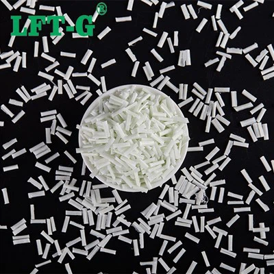
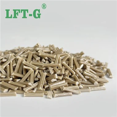
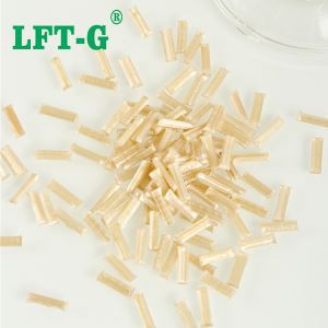
Long-fiber thermoplastics are not just "plastics with longer fibers." They are a fundamentally different class of materials that require a different approach to mold design. The fibers-typically 10–12 mm in the pellet-must survive the molding process and retain sufficient length to form a reinforcing network within the part. If the mold geometry breaks fibers, causes poor orientation, or creates stress concentrations, the part will underperform.
This guide covers 5 critical mold design principles for LFT-from gate design to venting-and provides concrete recommendations based on industry best practices and material science.

Principle 1: Gate Design - Where Fiber Orientation Begins
The gate is the single most important feature in an LFT mold. It determines both fiber orientation (which affects mechanical properties) and fiber length retention (which affects overall reinforcement).
The basic rule is simple: fibers align in the flow direction. If your part experiences tensile stress along a specific axis, orient the gate so that the flow direction aligns with that stress axis. If the part has multi-directional stress, consider multiple gates or a film gate to create more balanced orientation.
Gate size is equally critical. A gate that is too small creates high shear rates that break fibers. The gate should be at least 70–80% of the part wall thickness in diameter for pin gates, and at least 1.5–2.0 mm thick for edge gates. For high-fiber-content grades (40–50%), increase gate dimensions by 20–30%.
Best Practice
- Use fan gates or film gates for large parts to distribute flow and reduce shear
- Position gate at the thickest section of the part
- Gate size: ≥ 1.5 mm for edge gates, ≥ 2.5 mm for pin gates (PA/PPS/PEEK grades require larger gates)
- Use radiused transitions from runner to gate
Avoid
- Pin gates under 1.5 mm - they shred fibers
- Sharp corners in runner-to-gate transitions
- Gating at a thin section - causes flow hesitation and premature freeze-off
- Submarine gates for LFT (severe shear)
Principle 2: Wall Thickness - Uniformity Is Everything
Recommended Wall Thickness Ranges for LFT Materials

LFT is extremely sensitive to wall thickness variations. Unlike short-fiber compounds, LFT fibers cannot easily reorient or redistribute across thickness changes. Abrupt transitions create turbulence, fiber disorientation, and differential shrinkage - all of which lead to warpage and stress concentration.
The recommended wall thickness for most LFT parts is 2.0 to 4.0 mm. Below 1.5 mm, fibers are physically constrained and cannot orient properly; above 5.0 mm, cooling becomes uneven and cycle times increase significantly.
Where thickness changes are unavoidable (e.g., ribs meeting walls), use gradual transitions with a taper ratio of 2:1 or less (length of transition at least twice the thickness difference).
Critical rule: Wall thickness should not vary by more than 25% across the part. If you need thick sections for strength, consider using ribs instead of increasing nominal wall thickness.
Principle 3: Rib Design - Add Stiffness Without Sink Marks

Ribs are the most efficient way to add stiffness to an LFT part without increasing wall thickness. But incorrectly designed ribs cause sink marks, voids, and fiber breakage.
The golden rule for LFT rib design is the 0.5–0.7 rule: rib base thickness should be 50% to 70% of the nominal wall thickness. For a 3.0 mm wall, rib base thickness should be 1.5–2.1 mm. This prevents sink marks on the opposite surface while still providing structural benefit.
Rib height should be limited to 3× the nominal wall thickness (e.g., 9 mm maximum for a 3 mm wall). Taller ribs increase the risk of buckling under load and create cooling challenges.
Root radius is critical: use a minimum radius of 0.5× wall thickness (e.g., 1.5 mm radius for 3 mm wall). Sharp corners act as stress risers and cause fiber breakage during filling.
Principle 4: Draft Angle - Don't Forget the Shrinkage
LFT materials have lower shrinkage than short-fiber compounds - but they also have higher friction against mold steel. The combination means ejection forces are higher, and the risk of part deformation or surface damage is greater.
Recommended draft angles for LFT:
| Surface Type | Core Side (Internal) | Cavity Side (External) |
|---|---|---|
| Smooth / Polished | 1.5° – 2.0° | 1.0° – 1.5° |
| Textured (MT 11000–12000) | 3.0° – 4.0° | 2.5° – 3.5° |
| Deep ribs/bosses (> 3× wall) | 2.0° – 3.0° | 1.5° – 2.5° |
Note that PA-based LFT materials (which absorb moisture and swell) require additional draft - add 0.5° to the values above for PA6, PA66, and PPA grades.
Principle 5: Venting - Let the Air Out, Keep the Quality In
Venting is often overlooked in LFT mold design - but it is one of the most common sources of quality problems. LFT materials contain significant amounts of entrapped air (between fibers and in the pellet) that must escape during filling. If it doesn't, you get burn marks, short shots, and surface defects.
The critical parameter is venting depth. LFT vent depths are shallower than for short-fiber materials because the long fibers can physically bridge across the vent. Recommended vent depths:
| Material | Recommended Vent Depth |
|---|---|
| PP-LFT | 0.015 – 0.025 mm |
| PA-LFT | 0.010 – 0.020 mm |
| PPS / PEEK-LFT | 0.005 – 0.015 mm |
Venting should be placed at the end of fill, weld line locations, and blind cavities. Use a venting land length of 3–5 mm followed by a deeper relief channel (0.5–1.0 mm) to allow gas to escape freely after passing the vent.
Pro tip: For PA and PPS grades, which produce more gas during molding, increase the number of vent locations by 30–50% compared to what you would use for PP. Add vents to runner ends - runners often trap air that affects cavity filling.
LFT Team: Ready to Solve Your Mold Design Challenges
Our engineering team offers mold design reviews, flow simulation, material selection, and on-site troubleshooting for automotive, aerospace, and industrial applications. From new tooling to existing mold optimization - we help you avoid costly mistakes and achieve consistent part performance. Reach out for a free consultation.

Get LFT mold design engineering support
Xiamen LFT Composite Plastic Co., Ltd. is a global supplier of long-fiber-reinforced thermoplastics with 20+ years of innovation. We specialize in LFT‑PP, LFT‑PA, LFT‑PPS, and LFT‑Elastomers – offering high‑strength, lightweight alternatives to metal for automotive, aerospace, and industrial applications. Our engineering team provides mold design review and process optimization support for customers worldwide.