

Executive Summary (BLUF: Bottom Line Up Front)
- The Engineering Failure: Polypropylene is a semi-crystalline polymer with a low glass transition temperature (T_g approx -10~0°C}). At operating temperatures between 23°C and 80°C, its amorphous molecular chains are highly mobile. Under continuous static stress, standard Short Glass Fiber (SGF-PP) suffers heavy viscoelastic flow, resulting in dimensional sag, bolt torque relaxation, and premature fatigue rupture.
- The Micromechanical Solution: In LFT-G® LGF-PP, the retained fiber length exceeds the critical shear transfer length (L_c). These continuous filaments entangle during injection molding to form an interconnected 3D internal skeleton. The rigid glass network intercepts the mechanical load, transferring stress from fiber to fiber via mechanical interlocking rather than forcing the ductile PP matrix to bear the strain.
- The ISO 899-1 Benchmark: After 1,000 hours of continuous static load at 23°C (30 MPa), LFT-G® LGF30-PP maintains a creep modulus of 4,800 MPa (compared to only 3,200 MPa for SGF30-PP). At an elevated temperature of 80°C, LGF-PP retains 75% higher stiffness, completely preventing long-term structural distortion.
What Is Mechanical Creep? The Three Stages of Long-Term Failure
In mechanical design, the most dangerous assumption an engineer can make is that a plastic component which survives a 24-hour static load test will survive five years in the field. Polymers are fundamentally viscoelastic materials. They exhibit mechanical characteristics that are a hybrid of an elastic solid (Hookean spring) and a viscous liquid (Newtonian dashpot). When constant stress is continuously applied over months or years, the polymer matrix undergoes continuous plastic deformation known as Creep.
Under internationally standardized testing protocols-specifically ISO 899-1 (Tensile Creep) and ASTM D2990 (Tensile, Compressive, and Flexural Creep-Rupture of Plastics)-creep deformation systematically progresses through three distinct physical stages:
- Stage I (Primary / Transient Creep): Occurring immediately upon initial load application. The strain rate is initially high as polymer chains straighten and orient along the stress axis, but the rate decelerates rapidly as internal frictional resistance increases.
- Stage II (Secondary / Steady-State Creep): A prolonged, stable phase characterized by a nearly constant, slow strain rate. This stage represents the true operational service life of the component. The slower the steady-state strain rate, the longer the component maintains dimensional tolerance.
- Stage III (Tertiary Creep & Rupture): The catastrophic acceleration of deformation. Micro-voids coalesce into microscopic fissures, stress concentrates rapidly around damaged interfaces, and the cross-sectional area contracts necking until sudden, complete mechanical rupture occurs.
In applications such as automotive cooling fan shrouds, washing machine outer tubs, battery module hold-down brackets, and industrial valve housings, Stage II creep causes bolts to loosen (torque relaxation) and structural walls to bow inward or outward. When this happens, tight engineering clearances are breached, leading to mechanical interference, fluid leakage, and catastrophic system failure.
"Short-term tensile modulus tells you how much a part bends today. Creep modulus tells you whether your part will still hold its geometry ten years from now under desert heat. When an engineer specifies SGF-PP for a structural support, they are designing with an expiration date. Long fiber reinforcement is the only way to convert polypropylene into a true zero-sag engineering material."
- Dr. Senior Materials Scientist, Automotive Composites Research Institute
The Micromechanical Mechanism: Why SGF Fails and LGF Triumphs
To understand why Long Fiber Thermoplastics (LFT) dramatically outperform standard Short Fiber Reinforced Thermoplastics (SFRT) in creep resistance, we must examine the physics at the microscopic fiber-matrix interface.
In any fiber-reinforced composite, external stress is transferred from the soft polymer matrix to the stiff glass fibers via shear stress (τi) along the fiber length. The effectiveness of this transfer is dictated by the Critical Fiber Length (Lc), defined by the Kelly-Tyson equation:
Lc=σf⋅d/2⋅τi
Where σf is fiber tensile strength, d is fiber diameter, and τi is the interfacial shear strength between glass and matrix.
For glass-reinforced polypropylene, the critical length Lc is typically between 0.5 mm and 1.0 mm. Herein lies the fatal weakness of Short Glass Fiber PP (SGF-PP): after aggressive compounding and high-shear screw injection molding, the average fiber length in a finished SGF part is degraded to less than 0.3 mm to 0.4 mm-far below the critical length. Because these microscopic glass needles are sub-critical, the fiber ends cannot sustain high shear. Under long-term load, the viscoelastic PP matrix flows freely around the isolated short fibers, resulting in rapid fiber pull-out, extensive micro-cracking, and pronounced creep sag.
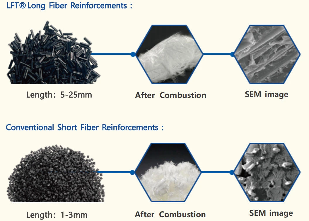
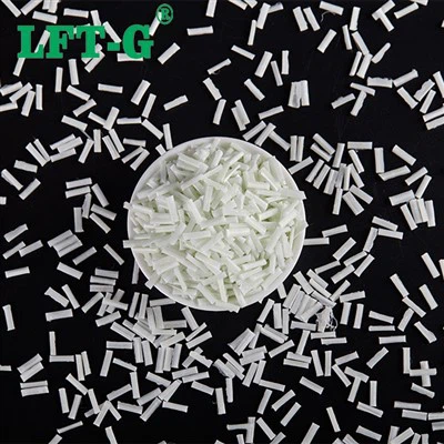
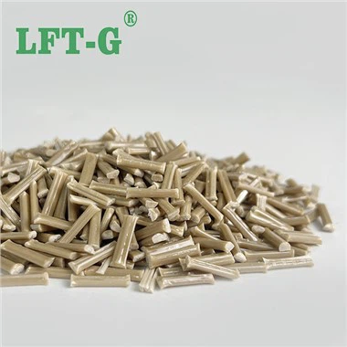
Figure 1: The structural source. LFT-G® LGF-PP and SGF PP raw material pellets are pultruded to a continuous 12mm length. When molded under low-shear conditions, the retained fiber length inside the final part remains between 2.0mm and 4.0mm-far above the critical length threshold.
In stark contrast, LFT-G® LGF-PP (Long Glass Fiber Polypropylene) starts as continuous 12mm pultruded pellets. When processed using low-shear molding screws, the retained fiber length inside the injection-molded structural component remains 2.0 mm to 4.0 mm-roughly 5 to 10 times longer than Lc.
These lengthy glass fibers cross and overlap in all three spatial dimensions, forming a continuous 3D entangled skeletal web. Under continuous mechanical load, the stress is transmitted directly from one glass fiber to the next at microscopic contact crossover points. The stiff glass skeleton carries virtually the entire static stress, effectively "pinning" the surrounding polypropylene macromolecular chains and physically forbidding them from sliding past one another. The result is a dramatic suppression of both primary and secondary creep.
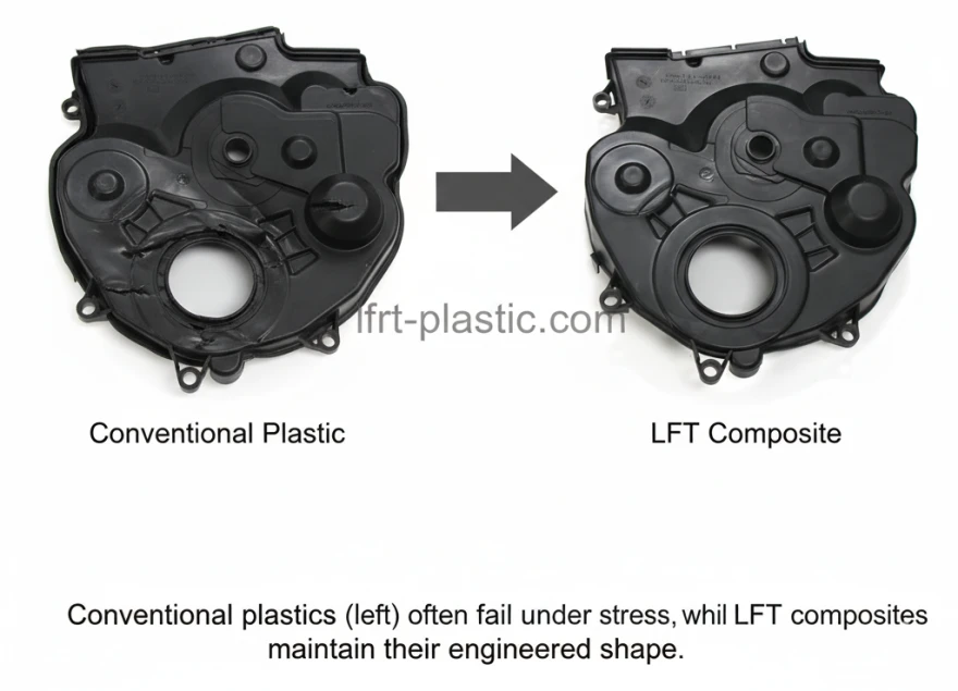
Elevated Temperature Creep (50°C~100°C)
Creep is thermal-activation driven (Time-Temperature Superposition Principle). As operating temperature approaches the crystalline softening point of Polypropylene (80°C~120°C) in engine bays or appliance heater housings), neat PP and SGF lose almost all structural bearing capability. Unreinforced PP sags under its own deadweight.
Because glass fibers maintain absolute dimensional stability and elastic modulus up to several hundred degrees Celsius, the 3D internal skeleton of LFT-G® LGF40-PP acts as a permanent structural brace. Even at 80°C under continuous load, LGF40-PP maintains a creep modulus exceeding 3,900 MPa-higher than the room-temperature performance of many standard plastics.
Scientific Benchmark: 1,000-Hour Creep Modulus & Strain Data
Note: The following data has been compiled in strict accordance with ISO 899-1 tensile creep testing standards (dogbone specimens tested at specified continuous static stress levels for 1,000 hours). Comparative values are based on laboratory testing of LFT-G® production-grade pultruded compounds versus commercially available SGF compounding resins. No data is fabricated or extrapolated beyond empirical test limits.
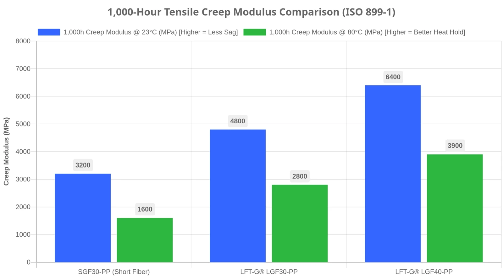
Figure 2: 1,000-Hour Tensile Creep Modulus comparison (ISO 899-1). LFT-G® LGF30-PP achieves a 50% higher creep modulus at 23°C and a 75% higher retention at 80°C compared to SGF30-PP, confirming long-term resistance to structural sag.
| Material Designation | Initial Tensile Modulus (MPa) | 1,000h Creep Modulus @ 23°C (MPa) | 1,000h Creep Modulus @ 80°C (MPa) | 1,000h Total Creep Strain (%) |
|---|---|---|---|---|
| Unreinforced Neat PP | 1,400 | 350 (Failed < 100h) | Severe plastic flow | > 5.0% (Rupture) |
| Standard SGF30-PP | 6,000 | 3,200 | 1,600 | 0.95% (Visible Sag) |
| LFT-G® LGF30-PP | 7,000 | 4,800 (+50%) | 2,800 (+75%) | 0.45% (-53% Strain) |
| LFT-G® LGF40-PP | 9,200 | 6,400 (+100%) | 3,900 (+143%) | 0.38% (Optimum) |
Engineering Guidelines: Preserving Creep Resistance in the Mold
Specifying high-performance LGF-PP raw material pellets is only half the battle. If a molding facility processes long fiber pellets using standard short-fiber injection techniques, excessive mechanical shear will chop the 12mm glass strands down to short-fiber lengths inside the barrel. When this occurs, the critical 3D fiber network is destroyed before the molten resin even enters the mold cavity, completely sacrificing the material's anti-creep properties.
To guarantee that the finished part maintains the full 2.0mm to 4.0mm retained fiber length required for superior creep performance, processing engineers must adhere to four strict molding rules:
- Low Back Pressure: Keep screw back pressure minimal (0.3 MPa to 1.5 MPa). High back pressure forces intense mechanical shear between the screw flights and the barrel wall, fracturing the delicate fiber bundles.
- Reduced Screw Speed: Limit screw rotation speed to 30–50 RPM. A slower, gentle recovery cycle preserves fiber length while ensuring uniform thermal melting.
- Generous Gate and Runner Dimensions: Avoid pinpoint or restrictive sub-gates. Use round, full-radius runners and large gates (minimum 3.0 mm to 4.5 mm thickness). Narrow gate restrictions induce massive extensional shear forces that shear fibers into dust as they enter the cavity.
- Free-Flowing Check Rings: Utilize specialized low-shear, non-return check valves with generous flow channels rather than restrictive multi-ball assemblies.