
Why LFT's 3D Fiber Network Changes Everything
A Visual Guide to What Long Fibers Actually Do Inside Your Parts
If you've ever specified fiber-reinforced thermoplastics, you know the question: short fiber or long fiber? The data sheets show higher numbers for LFT - higher impact strength, higher stiffness, better creep resistance. But why? What's actually happening inside the material that makes long fibers so much more effective?
The answer lies in the 3D fiber network - a continuous, entangled skeletal structure that forms inside the part during injection molding. This network is the fundamental reason LFT outperforms short-fiber compounds across virtually every mechanical metric. And once you visualize it, you'll never look at fiber reinforcement the same way again.
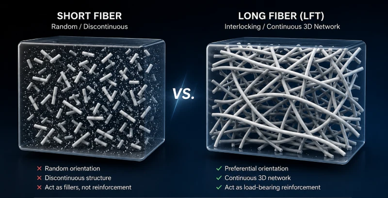
Figure 1. Short fibers (left) are randomly dispersed and disconnected. Long fibers (right) form an interlocking 3D skeletal network that carries load across the entire part.
The Numbers: Why Length Matters

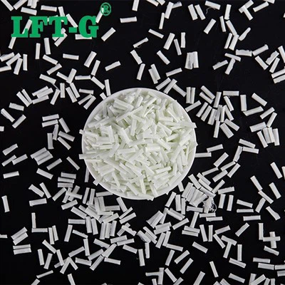
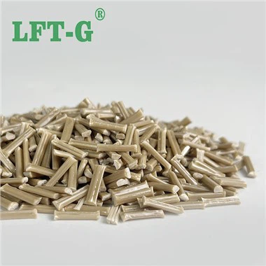
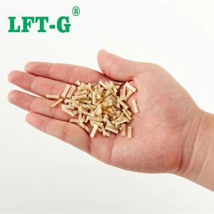
The difference starts with the pellet. Short-fiber compounds contain fibers that are 0.2–0.5 mm long. LFT pellets contain fibers that are 6–25 mm long. In a typical 30% glass-filled compound, that's a 12× to 50× difference in fiber length before the material even enters the mold.
But the critical difference is what happens during molding. In an LFT pellet, the fibers are continuous - 10–12 mm in length, aligned and impregnated with resin. During injection, these long fibers flow together and interlock, forming a 3D continuous skeletal fiber network. Short fibers, by contrast, are already broken - usually less than 1 mm - and act merely as fillers, not structural reinforcement.
Key takeaway: Short fibers are dispersed. Long fibers are connected. Dispersion adds modest reinforcement. Connection creates a structural skeleton.
The 3D Network: What It Actually Looks Like

To understand the 3D network, imagine a handful of sand versus a piece of rebar mesh. Sand particles are individual, disconnected, and slide past each other under load. Rebar is continuous, interlocked, and distributes stress across its entire structure. The same principle applies to fibers in thermoplastics.
In an LFT part, the long fibers form an entangled, three-dimensional skeleton that runs throughout the component. This network:
- Restricts plastic flow - the network resists deformation under load
- Distributes stress evenly - load is shared across the entire fiber network, not concentrated at individual fiber ends
- Prevents crack propagation - cracks must navigate around and through the network, requiring significantly more energy
- Maintains integrity at extreme temperatures - the network holds together even when the matrix softens
This network is not theoretical. If you burn away the resin from an LFT part, the glass fibers remain as a self-supporting skeleton - a physical 3D structure that retains the shape of the original part. Short-fiber parts, under the same test, collapse into a pile of disconnected fibers with no structural integrity.
Visual proof: Burn off the resin. LFT leaves a standing fiber skeleton. Short-fiber leaves a pile of dust. That's the difference between structural reinforcement and mere filler.
What the Network Delivers: Performance That Matters
The 3D network translates directly into measurable performance advantages that engineers care about:
LFT-G® PP LGF40 delivers 45 kJ/m² Charpy notched impact vs. 18 kJ/m² for short-fiber PP GF40 at 23°C
At -40°C, LFT-G® PP LGF40 retains 38 kJ/m² impact strength - short-fiber drops to just 5 kJ/m²
The 3D network resists progressive deformation under sustained load and outlasts short-fiber compounds in cyclic fatigue
The network also delivers exceptional dimensional stability - low warpage, low shrinkage, and consistent part-to-part quality. And because the fibers are fully encapsulated in the resin matrix, LFT parts have smooth, fiber-free surfaces - no glass protrusion, no post-processing.
The Practical Takeaway: Design with the Network in Mind
Understanding the 3D network changes how you design. Short-fiber compounds are isotropic - properties are roughly the same in all directions. LFT is anisotropic - properties follow the fiber network, which follows the flow of the melt.
This means:
- Gate placement matters - flow direction determines fiber orientation and therefore strength direction
- Weld lines are structural - they disrupt the network and should be placed in low-stress areas
- Thick sections are actually beneficial - more space for the network to form and interlock
- Ribs and bosses integrate seamlessly - the network flows around features, reinforcing them naturally
Design for LFT is not about avoiding fiber breakage - it's about enabling the network. Use large gates, slow injection speeds, and moderate back pressure to preserve fiber length and allow the network to form fully.
The Bottom Line
Short fibers are sand - they fill space but don't connect. Long fibers are rebar - they form a continuous skeleton that carries load, resists impact, and maintains integrity across temperature extremes and millions of cycles. LFT-G® delivers that network in every pellet - from PP to PA to PPS to PEEK, from 20% to 60% fiber content. The network is what makes LFT LFT. And it's why LFT outperforms short-fiber compounds in every application where performance matters.

LFT team: ready to help you design with the network
Xiamen LFT Composite Plastic Co., Ltd. is a global supplier of long-fiber-reinforced thermoplastics with 20+ years of innovation. We specialize in LFT‑PP, LFT‑PA, LFT‑PPS, and LFT‑Elastomers – offering high‑strength, lightweight alternatives to metal for automotive, aerospace, industrial, and sporting goods applications. Our engineering team provides material selection, mold design review, and on-site technical support for customers worldwide - from concept to production. Reach out for a free consultation.